Autoclaves are critical equipment in pharmaceutical, biotechnology, and medical device industries, used for sterilizing equipment, materials, and products. Ensuring their performance through a rigorous qualification process is essential for maintaining sterility assurance and compliance with regulatory standards. Autoclave qualification encompasses a series of documented tests and procedures that verify the equipment's ability to consistently produce sterile outcomes under defined operating conditions.
This abstract provides a comprehensive overview of autoclave qualification, including its purpose, regulatory framework, qualification phases, testing protocols, documentation requirements, and industry best practices.
Purpose of Autoclave Qualification
The primary goal of autoclave qualification is to demonstrate that the sterilization process is effective, reproducible, and compliant with regulatory expectations. It ensures:
Consistent sterilization of materials and products
Elimination of microbial contamination
Validation of cycle parameters (temperature, pressure, time)
Assurance of product and patient safety
? Regulatory Framework
Autoclave qualification is governed by several international guidelines and standards, including:
FDA (21 CFR Part 211) ? Current Good Manufacturing Practice (cGMP)
EU GMP Annex 15 ? Qualification and Validation
ISO 17665 ? Sterilization of health care products
ICH Q8, Q9, Q10 ? Pharmaceutical development, risk management, and quality systems
USP <1229> ? Sterilization and sterility assurance
BS EN 285 - Sterilization ? Steam sterilizers ? Large sterilizers
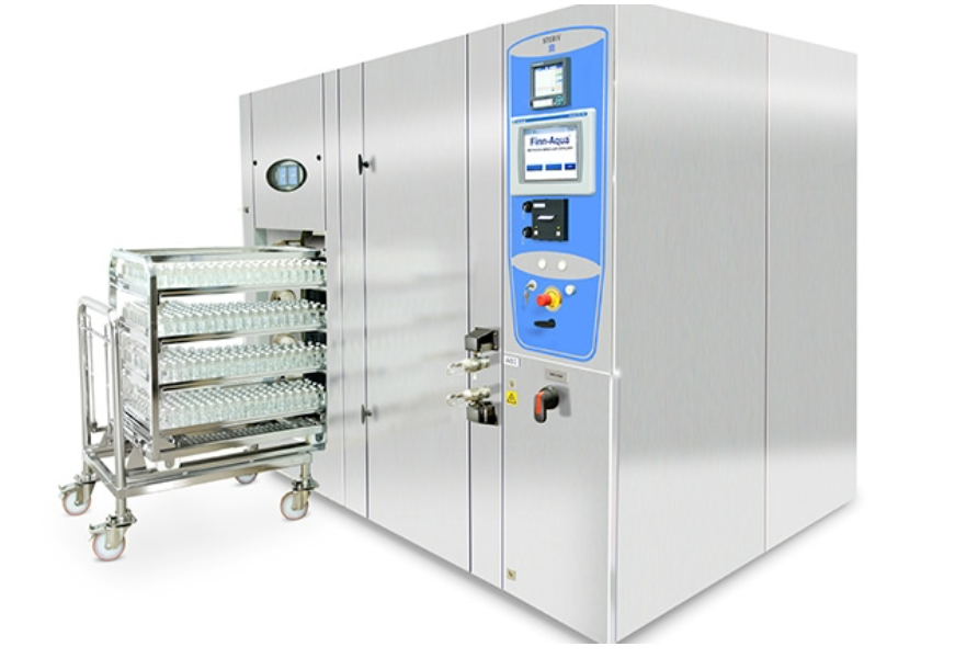
These regulations emphasize the importance of documented evidence, risk-based approaches, and lifecycle management of equipment.
Qualification Lifecycle
Autoclave qualification typically follows a structured lifecycle approach comprising four key phases:
1. Design Qualification (DQ)
Ensures the autoclave design meets user requirements and intended use
Involves reviewing specifications, drawings, and vendor documentation
Confirms compliance with applicable standards
2. Installation Qualification (IQ)
Verifies correct installation of the autoclave at the site
Checks utilities (steam, water, electricity), calibration of sensors, and safety features
Documents equipment serial numbers, software versions, and environmental conditions
3. Operational Qualification (OQ)
Tests the autoclave s functionality under empty load conditions
Verifies control systems, alarms, interlocks, and cycle parameters
Includes heat distribution studies using thermocouples and data loggers
4. Performance Qualification (PQ)
Demonstrates consistent performance with actual loads
Involves biological indicators (BIs) and chemical indicators (CIs)
Validates sterilization efficacy across different load configurations
Key Testing Protocols
Heat Distribution and Penetration Studies
Use thermocouples to map temperature across chamber and load
Identify cold spots and validate uniform heat penetration
Conduct multiple runs to ensure reproducibility
Biological Indicator (BI) Testing
Place BIs containing resistant spores (e.g., Geobacillus stearothermophilus) in worst-case locations
Post-cycle incubation to confirm spore kill
Establish sterility assurance level (SAL) of 10-6
Chemical Indicator (CI) Testing
Use color-changing indicators to verify exposure to sterilization conditions
Supplement BI testing for visual confirmation
Bowie-Dick Test
Detects air removal efficiency in pre-vacuum cycles
Ensures steam penetration and absence of air pockets
Leak Rate Test
Assesses chamber integrity under vacuum
Ensures no leakage that could compromise sterilization
Documentation and Reporting
Comprehensive documentation is essential for qualification. Key documents include:
Qualification protocols and reports (DQ, IQ, OQ, PQ)
Calibration certificates
Cycle development and validation data
BI and CI test results
Deviation reports and corrective actions
Change control records
All records must be reviewed and approved by quality assurance (QA) and maintained for audits and inspections.
? Cycle Development and Optimization
Before PQ, cycle development is performed to determine optimal sterilization parameters. This involves:
Testing various load types and configurations
Establishing minimum exposure times and temperatures
Identifying worst-case scenarios
Ensuring product integrity post-sterilization
Cycle parameters are finalized based on successful validation runs.
? Risk Management and Worst-Case Scenarios
Risk-based approaches are used to identify critical parameters and worst-case conditions. This includes:
Heaviest and densest loads
Hard-to-sterilize materials (e.g., porous items, liquids)
Locations with poor steam penetration
Testing under these conditions ensures robustness of the sterilization process.
Requalification and Maintenance
Autoclaves require periodic requalification to maintain validated status. Triggers for requalification include:
Major repairs or modifications
Relocation of equipment
Changes in load types or cycle parameters
Scheduled intervals (e.g., annually)
Routine maintenance, calibration, and preventive checks are essential for continued performance.
Common Challenges and Solutions
Inconsistent Temperature Distribution
Solution: Adjust load configuration, increase exposure time, or modify cycle parameters
BI Failures
Solution: Investigate root cause, repeat testing, and implement corrective actions
Equipment Malfunctions
Solution: Perform troubleshooting, document deviations, and requalify post-repair
Case Study: Autoclave Qualification in a Pharmaceutical Manufacturing Facility
A pharmaceutical company implemented autoclave qualification for sterilizing glass vials and stainless-steel components. Key steps included:
DQ: Reviewed vendor specs and ensured compliance with ISO 17665
IQ: Verified installation, utilities, and calibration
OQ: Conducted heat distribution studies with 12 thermocouples
PQ: Validated three load types using BIs and CIs in worst-case locations
Outcome: Achieved consistent SAL of 10-6 and approved sterilization cycles
Conclusion
Autoclave qualification is a critical component of pharmaceutical and biotech manufacturing, ensuring the sterility of products and compliance with global standards. A structured approach involving DQ, IQ, OQ, and PQ, supported by robust testing and documentation, provides assurance of equipment performance and patient safety. Continuous monitoring, requalification, and risk management are essential for maintaining validated status throughout the equipment lifecycle.
Sterilization methods
Need support in Autoclave qualification/ Validation Reach out at IncepBio ? Let's build cleanrooms that stay clean.
GMP Cleanroom Classifications: Grade A, B, C and D
Cleanrooms are an integral part of pharmaceutical and medical product manufacturing. They provide tightly controlled environments that reduce the risk of contamination from airborne particles and microorganisms.
Regulatory authorities worldwide have established detailed guidelines for cleanroom classification and control to maintain the highest product quality and patient safety standards.
Introduction to GMP Cleanroom Classifications
Good Manufacturing Practice (GMP) guidelines for pharmaceutical cleanrooms were established to ensure product safety, purity, and efficacy. These guidelines are designed to minimize the risk of contamination from particulates, microorganisms, and pyrogens during sterile manufacturing processes such as preparation, filling, and packaging.
GMP cleanroom requirements are comprehensive, ranging from facility design and environmental controls to personnel behavior, gowning, and cleaning procedures. One of these requirements is the cleanroom classification system, a structured method for defining cleanliness levels based on airborne particulate concentration and microbial control.

Two major standards form the basis for pharmaceutical cleanroom classification:
ISO 14644-1, which defines cleanroom classes (ISO Class 5 to ISO Class 9) based solely on airborne particle concentrations.
EU GMP Annex 1?(Grade A, B, C, D), which applies ISO principles to pharmaceutical environments and introduces additional microbial limits, gowning expectations, and operational state distinctions ("At Rest and "In Operation?).
GMP Cleanroom Classes and ISO Equivalents
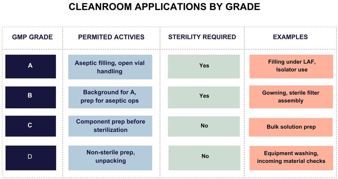
GMP cleanrooms are categorized into four grades Grade A, B, C, and D based on the criticality of operations performed within each area. These grades correlate with ISO classes, providing a harmonized reference for particle limits.
Grade A Cleanroom
Grade A is reserved for the most critical operations, such as aseptic filling, compounding, and open handling of sterile products.
ISO Equivalent: ISO Class 5 (both at rest and in operation)
Particle Limit: = 3,520 particles = 0.5 ?m/m?
Grade B Cleanroom
Grade B areas serve as the background environment for Grade A zones and support aseptic processing.
ISO Equivalent: ISO Class 5 (at rest), ISO Class 7 (in operation)
Particle Limits:
At rest: = 3,520 particles = 0.5 ?m/m?
In operation: = 352,000 particles = 0.5 ?m/m?
Grade C Cleanroom
Grade C cleanrooms are used for less critical stages, such as preparing solutions and handling components before sterilization.
ISO Equivalent: ISO Class 7 (at rest), ISO Class 8 (in operation)
Particle Limits: = 352,000 particles = 0.5 ?m/m?
Grade D Cleanroom
Grade D areas are designated for the least critical stages of sterile drug production, including initial handling and washing of components.
ISO Equivalent: ISO Class 8 (at rest and in operation)
Particle Limit: = 3,520,000 particles = 0.5 ?m/m?
Cleanroom Particle Limits and Operational States
Cleanroom classifications are defined by the maximum allowable concentration of airborne particles, typically = 0.5 ?m and = 5.0 ?m in size. Regulatory guidance, including Annex 1?and ISO 14644-1, requires classification and routine monitoring for Grades A through C conditions.
For Grade D, only "At Rest limits are predefined; "In Operation limits must be set by the manufacturer based on risk assessment.
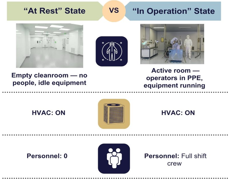
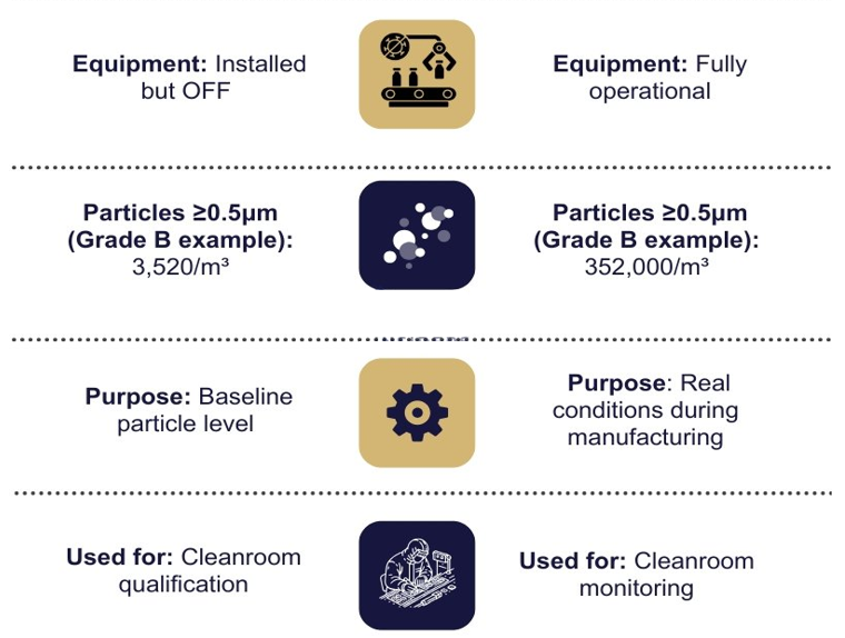
"At Rest State: Establishing Baseline Cleanliness
The "At Rest state signifies a moment of readiness without active manufacturing operations. All utilities, including the vital Heating, Ventilation, and Air Conditioning (HVAC) system, are installed and operational in this phase.
Equipment is meticulously arranged but not yet set into motion, and notably, no personnel inhabit the room. This state establishes a baseline for cleanliness, offering insights into the environment s inherent purity without the influence of human activities or equipment operation.
Cleanroom Classification Chart No.1: Total Particle Limits for "At Rest State
| Cleanroom Class |
≥ 0.5 µm (Particles/m³) |
≥ 5 µm (Particles/m³) |
| A |
3,520 |
Not specified |
| B |
3,520 |
Not specified |
| C |
352,000 |
2,930 |
| D |
3,520,000 |
29,300 |
In Operation State: Real-world Cleanroom Dynamics
Contrasting with the quiescence of the "At Rest state, the "In Operation state encapsulates the full spectrum of cleanroom functionality. HVAC is not merely operational but fully engaged, equipment hums in its defined mode, and the cleanroom is bustling with the maximum number of personnel immersed in routine work.
This state reflects real-world manufacturing conditions, considering the dynamic factors introduced by human activities and equipment operations.
Cleanroom Classification Chart No.2: Total Particle Limits for In Operation State
| Cleanroom Class |
≥ 0.5 µm (Particles/m³) |
≥ 5 µm (Particles/m³) |
| A |
3,520 |
Not specified |
| B |
352,000 |
2,930 |
| C |
3,520,000 |
29,300 |
| D |
Not predetermined (a) |
Not predetermined (a) |
(a) For grade D, in-operation limits are not predetermined; the manufacturer should establish in-operation limits based on a risk assessment and routine data where applicable.
Microbial Contamination Limits and Monitoring in GMP Cleanrooms
While non-viable particle counts are central to cleanroom classification under ISO 14644-1, viable (microbial) contamination control is equally important in pharmaceutical GMP environments.
Cleanrooms must be monitored for microbial contamination using validated sampling methods and compared against established microbiological limits outlined in EU GMP Annex 1.
Microbial Contamination Limits by Cleanroom Grade
Microbial limits are defined by the number of colony-forming units (CFU) permitted in different sample types across cleanroom grades. These limits serve as alert/action thresholds for environmental monitoring programs and are evaluated during cleanroom qualification and routine monitoring.
Cleanroom Classification Chart No.3: Microbial contamination limits
| Cleanroom Class |
Air Sample (CFU/m³) |
Settle Plates (CFU/4 hours) |
Contact Plates (CFU/plate) |
| A |
<1 |
<1 |
<1 |
| B |
10 |
5 |
5 |
| C |
100 |
50 |
25 |
| D |
200 |
100 |
50 |
Viable Monitoring Methods Used in GMP Cleanrooms
Environmental monitoring programs utilize several methods to detect and trend microbial contamination in air and on surfaces:
1. Active Air Sampling
Pulls a defined air volume across a nutrient medium (e.g., agar strip).
Quantifies airborne microorganisms (CFU/m?).
Required in Grades A and B; recommended in C and D areas.
2. Passive Air Sampling (Settle Plates)
Petri dishes with growth media exposed to the cleanroom air for 2-4 hours.
Captures particles that settle by gravity.
Useful for detecting larger particles and surface contamination risk.
3. Surface Monitoring (Contact Plates and Swabs)
Contact plates are pressed against surfaces (e.g., walls, equipment) to detect microbial residues.
Swab samples are used in hard-to-reach areas or irregular surfaces.
Both methods assess cleaning effectiveness and risk of viable transfer.
4. Personnel Monitoring
Finger dabs and gown sampling (e.g., sleeve or chest area) with contact plates.
Helps assess the risk introduced by cleanroom operators, especially in Grades A & B.
Determining Sampling Locations:
The selection of sampling locations is a meticulous process guided by a comprehensive risk assessment. Several factors influence the determination of these locations:
Room Classification: The designated cleanliness level of different cleanroom areas plays a pivotal role in deciding the intensity and frequency of microbial sampling.
Air Visualization Studies: Insights gained from airflow visualization studies contribute to identifying areas where microbial contamination is more likely to occur.
Process and Operations Knowledge: A deep understanding of the manufacturing process and associated operations aids in pinpointing critical areas prone to microbial risks.
Considerations for Effective Sampling
Risk Assessment Integration: The sampling plan should be intricately woven into a comprehensive risk assessment, ensuring that higher-risk areas receive more thorough scrutiny.
Real-time Monitoring: In addition to periodic sampling, implementing real-time microbial monitoring systems provides continuous insights into the cleanroom's cleanliness status.
Prompt Corrective Actions: Deviations from microbial contamination limits should trigger immediate corrective actions, reinforcing a proactive stance against potential risks.
Applications of GMP Cleanroom Grades
Each GMP cleanroom grade is designed to support specific manufacturing activities based on the criticality of the process and the risk of contamination. Understanding the appropriate use of Grades A, B, C, and D is essential for maintaining compliance with Annex 1?and ensuring product safety in pharmaceutical production.
Grade A Cleanroom Applications
Grade A areas provide the highest level of contamination control and are used for critical aseptic operations. These zones require unidirectional airflow?(e.g., laminar air flow cabinets or isolators) and are typically maintained under positive pressure with strict particulate and microbial limits.
Common use cases include:
Aseptic filling of sterile products
Aseptic compounding and mixing
Loading and unloading of sterilizers (e.g., autoclaves or lyophilizers)
Replenishment of sterile bulk, containers, or closures
Staging of sterile primary packaging materials
Assembly of sterile connections for single-use systems
Note: These operations usually occur under ISO Class 5 (Grade A) laminar flow units within a Grade B background.
Grade B Cleanroom Applications
Grade B environments act as the background for Grade A zones, supporting aseptic manufacturing processes. These areas are essential in maintaining product sterility by preventing the ingress of contaminants during material and personnel transfers.
Typical applications:
Preparation and staging of materials for Grade A processing
Gowning rooms adjacent to aseptic core areas
Transfer of sterile equipment into Grade A zones
Cleaning and sanitization of tools used in aseptic filling
Assembly of sterile filtration systems before use
Note: Grade B areas are usually maintained at ISO Class 5 at rest and ISO Class 7 in operation.
Grade C Cleanroom Applications
Grade C cleanrooms support less critical but still controlled manufacturing steps. These areas are suitable for operations that involve exposing products or components prior to sterilization and preparing solutions and intermediates.
Common uses include:
Weighing and dissolving raw materials
Preparation of bulk solutions to be sterilized
Filling of products that will undergo terminal sterilization
Assembly of components for later sterilization
Note: ISO Class 7 at rest, ISO Class 8 in operation. Monitoring is essential but less frequent than in higher-grade areas.
Grade D Cleanroom Applications
Grade D environments are designed for basic cleanroom control, typically for initial or final processing steps after sterilization. While these zones do not require the same degree of cleanliness as higher grades, they still help reduce contamination in adjacent areas.
Key activities:
Washing and drying of equipment and components
Initial unpacking and inspection of raw materials
Final assembly of closed systems prior to sterilization
Cleaning and storage of reusable tools
Assembly of sterile connectors under closed conditions
Grade D zones are equivalent to ISO Class 8 and are often entry points into higher-grade areas.
Pharmaceutical Cleanroom Design Considerations
Adhering to GMP cleanroom design principles ensures that all elements - from airflow and filtration to zoning and material finishes - are optimized to minimize contamination risks throughout manufacturing. GMP-compliant cleanrooms must be built and maintained to support risk-based contamination control and maintain a consistent control state.
Airflow Control and Cleanroom Air Change Rates
Proper airflow design is the foundation of contamination prevention. Air must be supplied, filtered, and exhausted at a rate sufficient to dilute and remove particles generated by equipment, processes, and personnel.
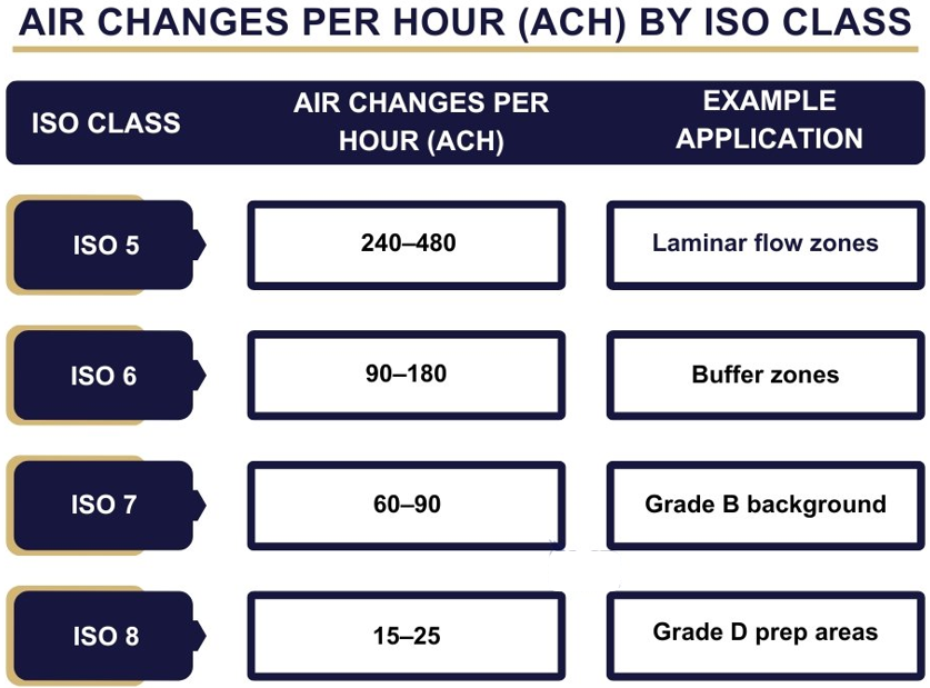
ACH Recommendations by ISO Class
Air Changes per Hour (ACH) refers to how often the cleanroom air is replaced. Higher ISO classes require frequent air changes to maintain low particle counts and short recovery times.
Note: Air change rates can exceed 600 ACH for Grade A laminar airflow zones.
Laminar vs. Turbulent Flow Patterns
Laminar (unidirectional) flow delivers air in a straight path at uniform velocity, minimizing turbulence and carrying particles away from critical zones.
Required in Grade A environments
Typical velocity:?0.36-0.54 m/s
Turbulent flow mixes air within the room and is used in lower-grade areas (C/D) where strict unidirectionality is not necessary.
Note: Incorporating proper airflow visualization studies (e.g., smoke studies) ensures airflow patterns are maintained as designed.
Filtration Systems
Cleanroom ventilation systems use high-efficiency filters to control both viable and non-viable particles.
HEPA/ULPA Filter Classification and Integrity Testing
HEPA (High-Efficiency Particulate Air) filters remove >=99.97% of particles =0.3 µm.
ULPA (Ultra-Low Penetration Air) filters remove >=99.9995% of particles =0.12 µm.
Grade A/B zones require?100% filter coverage with regular integrity testing using DOP/PAO aerosol challenge tests (per ISO 14644-3 or EN 1822).
Filter Change Frequency
Based on differential pressure readings, particle monitoring trends, and manufacturer recommendations
HEPA filters are typically replaced every 1-3 years or as part of a preventive maintenance program
Pressure Differentials and Room Zoning
An essential element of cleanroom contamination control is the maintenance of proper pressure differentials between classified zones.
Pressure Cascade Concept
Maintaining positive pressure differentials between rooms of different cleanliness prevents contaminated air from entering critical areas.
Grade A > Grade B > Grade C > Grade D
Recommended pressure differential:>=10-15 Pa
Cleanroom Zoning Principles
Cleanrooms must be logically zoned to support personnel, and material flows while maintaining cleanliness boundaries.
Airlocks for personnel and materials
Separate pathways for "clean" and "dirty" processes
Unidirectional flow of materials to minimize cross-contamination
Note: Improper zoning is a frequent GMP inspection finding and should be validated during facility design.
Pharmaceutical Cleanroom Materials and Surfaces
Construction materials must support easy cleaning, resist chemical degradation, and avoid particle shedding.
Wall Panels: Non-porous, smooth, and flush; coated with epoxy or PVC
Flooring: Seamless, anti-static, and chemically resistant (e.g., PU floors)
Ceilings: Walkable panels in Grade C/D; sealed grid ceilings in A/B zones
Furniture: Stainless steel or powder-coated steel; easy to clean and non-shedding
Gowning Requirements by GMP Cleanroom Grades
Personnel are the greatest source of contamination in cleanrooms. Gowning protocols must be tailored to the classification and aligned with Annex 1 expectations.
Table: PPE Required per GMP Cleanroom Grade
Note: Gowning must be performed in dedicated changing rooms with zoning and step-over barriers to separate clean and unclean areas.
GMP Cleanroom Testing Parameters
Once a cleanroom is built and classified, it must undergo performance tests to verify that it functions within the defined specifications. These tests are crucial for initial qualification (OQ/PQ) and form the basis for routine requalification, trending, and regulatory inspections.
Non-viable particle monitoring using calibrated particle counters is essential for assessing cleanroom compliance with ISO 14644-1 limits and supporting routine environmental monitoring. Cleanroom testing ensures that critical parameters such as airflow, pressure differentials, and contamination containment perform as designed.
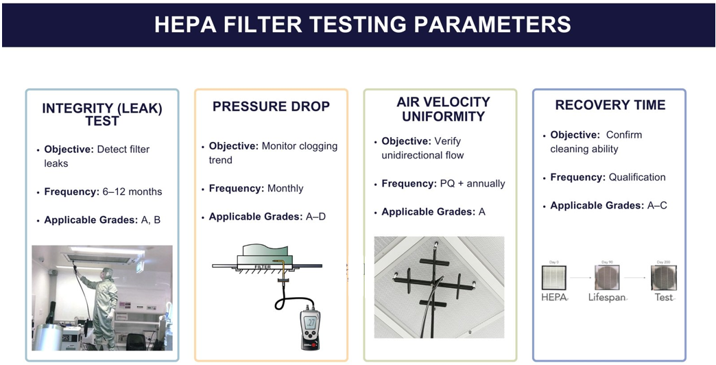
Installed Filter System Leakage and Integrity Testing
Ensuring the integrity of the filtration system is vital to prevent contaminants from entering the cleanroom. This aspect of the qualification process is crucial for ensuring the integrity of the filtration system within the cleanroom.
The filter system is designed to remove particles and contaminants from the air supply. HEPA filter leak test involves assessing whether the filters are properly installed, free of leaks, and capable of effectively trapping particles. This step is essential to prevent contaminants from entering the cleanroom and compromising the sterility of the manufacturing environment.
Tip: Regularly schedule and perform routine checks on filters to detect any potential leaks promptly.
Recommendation: Implement a preventive maintenance program to replace filters as needed and avoid unexpected failures during manufacturing operations.
Airflow Tests ? Volume and Velocity
Airflow characteristics play a significant role in maintaining the required air quality within the cleanroom. Volume and velocity tests assess the quantity and speed of air circulation. These tests ensure that the air within the cleanroom is exchanged at the specified rate and that the airflow is uniform.
Proper airflow is crucial for carrying away particles and contaminants and maintaining a controlled environment conducive to sterile product manufacturing.
Tools Used:
Hot-wire anemometers or vane anemometers (for velocity)
Flow hoods or balometers (for volumetric flow rate)
Target Specifications:
Laminar (unidirectional) flow zones: velocity typically between?0.36-0.54 m/s
Volumetric airflow must meet calculated ACH (Air Changes per Hour) requirements by ISO class
Velocity should be uniform across HEPA filter face?(±20% deviation is acceptable)
Tip: Conduct airflow tests at different locations within the cleanroom to ensure uniformity.
Recommendation: Testing is performed under both "At Rest and "In Operation states for areas classified as Grades A-C.
Air Pressure Difference Test
Maintaining pressure differentials between rooms of differing cleanliness levels prevents cross-contamination and helps control directional airflow. Positive pressure prevents contaminants from entering critical zones.
Directional Control:
Critical zones (e.g., Grade A) must be positively pressurized relative to adjacent lower-grade areas
Recommended differential:>=10-15 Pascals (Pa) between adjacent rooms
Monitoring and Deviations:
Pressure sensors or magnehelic gauges provide real-time readings
Deviations may indicate:
Door leakage
Filter blockage or fan failure
Incorrect damper or airlock settings
Tip: Clearly define and document the desired air pressure differentials between cleanroom areas.
Recommendation: Implement real-time monitoring systems to detect and address any deviations in pressure differentials promptly.
Airflow Direction Test and Visualization
Testing airflow direction validates whether the designed air movement patterns are maintained adequately during operation. Visualization confirms that air flows away from critical product and component zones.
Smoke Studies (Airflow Visualization)
Non-toxic fog (e.g., glycol or polyalphaolefin-based) is released near filters, work surfaces, or potential turbulence points
Used to:
Verify unidirectional airflow in Grade A areas
Identify air turbulence or reverse flow
Demonstrate protection of critical zones during personnel movement
Laminar Flow Validation
Laminar zones must show consistent, sweeping airflow with no backflow or dead zones
Required in aseptic filling, open vial handling, and media fill simulations
Tip: Use airflow visualization studies to involve personnel in understanding and confirming proper airflow patterns.
Recommendation: Conduct periodic refresher training for cleanroom personnel on the importance of maintaining correct airflow directions.
Microbial Airborne and Surface Contamination
Microbial contamination poses a significant risk in sterile product manufacturing. This part of the qualification process involves monitoring and limiting both airborne and surface microbial contamination.
Air and surface samples are taken and analyzed to ensure that microbial levels are within acceptable limits. This step is essential for maintaining the sterility of the environment and preventing the introduction of microorganisms that could compromise the quality of sterile products.
Tip: Establish a robust environmental monitoring program for continuous microbial surveillance.
Recommendation: Investigate any deviations from acceptable microbial limits promptly and implement corrective actions to address root causes.
Temperature and Relative Humidity Tests
Temperature and relative humidity levels are critical environmental factors in cleanrooms. These tests assess whether the cleanroom maintains the specified temperature and humidity conditions. Consistent control of these factors is essential for the stability of products and the prevention of conditions that could promote microbial growth or compromise product quality.
Tip: Place temperature and humidity sensors strategically across the cleanroom to capture variations in different areas.
Recommendation: Ensure that HVAC systems are calibrated and maintained to control temperature and humidity effectively.
Recovery Time Testing
The recovery test evaluates how quickly a cleanroom returns to its specified particle limits after a contamination event, such as door opening or personnel movement.
Clean-Up Period Definition:
Time required to reduce airborne particle levels to classification limits after an introduced load
Typical Benchmarks:
ISO 5?areas: recovery time typically<15 minutes
Higher ISO classes: longer recovery acceptable, depending on HVAC design
Tip: Simulate potential disruptions during routine operations to assess the cleanroom's real-world recovery capabilities.
Recommendation: Document and analyze recovery times, and use the data to optimize cleanroom protocols for minimizing downtime.
Containment Leak Test
In facilities handling cytotoxic, allergenic, or highly potent compounds, containment leak tests ensure that air and particles remain confined within designated zones.
Importance:
Protects both personnel and the environment
Required in negative-pressure rooms, isolators, and RABS (Restricted Access Barrier Systems)
Often includes smoke testing and filter integrity verification
Tip: Regularly review and update containment systems based on technological advancements and lessons learned from past incidents.
Recommendation: Conduct thorough training for personnel on the proper use and maintenance of containment equipment to minimize the risk of leaks.
Cleanroom Classification Comparisons: Annex 1, ISO, and US Standards
To ensure global harmonization and consistency, cleanroom classifications in GMP guidelines often align with international standards such as ISO and US Federal Standards. Let's compare cleanroom classifications according to Annex 1, ISO, and US standards:
Annex 1 Cleanroom Classifications
The EU GMP Annex 1 cleanroom grades A through D provide a structured approach to controlling contamination based on process criticality, with clear distinctions in particle and microbial limits.
It aligns with ISO 14644-1:2015 for cleanroom classifications. The grades and their associated ISO equivalents are as follows:
Grade A: ISO Class 5 at rest and in operation
Grade B: ISO Class 5 at rest, ISO Class 7 in operation
Grade C: ISO Class 7 at rest, ISO Class 8 in operation
Grade D: ISO Class 8 at rest and in operation
ISO Cleanroom Classifications
ISO 14644-1:2015 provides a comprehensive classification system for cleanrooms. The classifications are based on the maximum permitted concentration of airborne particles.
US Federal Standard 209E Cleanroom Classifications
The US Federal Standard 209E, although superseded by ISO 14644-1:2015, provides a historical reference for cleanroom classifications. The classifications are based on the number of particles per cubic foot. The US Federal Standard 209E classifications and their corresponding particle limits are as follows:
| ISO Class |
Max Particles/m³ |
| ISO 1 | 10 |
| ISO 2 | 100 |
| ISO 3 | 1,000 |
| ISO 4 | 10,000 |
| ISO 5 | 100,000 |
| ISO 6 | 1,000,000 |
| Class |
Max Particles/ft³ |
| Class 1 | 35 |
| Class 10 | 350 |
| Class 100 | 3,500 |
| Class 1,000 | 35,000 |
| Class 10,000 | 350,000 |
| Class 100,000 | 3,500,000 |
Note: FED-STD-209E was officially withdrawn in 2001 but is still widely referenced. It uses particle concentration per cubic foot, unlike ISO 14644 which measures per cubic meter.
Cleanroom Qualification and Validation Process
Qualification and validation are essential for demonstrating that a cleanroom consistently performs as intended, supports product quality, and complies with GMP and ISO 14644-1 requirements.
These activities provide documented evidence that the cleanroom environment can reliably meet its classification parameters under defined conditions, both for non-viable particle control and microbiological limits.
Documented cleanroom validation protocols must define the sequence of qualification activities (DQ, IQ, OQ, PQ) and be aligned with regulatory expectations and product-specific contamination risks.
Stages of Cleanroom Qualification
Cleanroom qualification is typically performed in four stages, each building upon the last to ensure facility readiness and operational reliability.
Design Qualification (DQ)
Verifies that the cleanroom design meets all regulatory, functional, and process requirements.
Includes layout drawings, zoning strategy, airflow direction, HVAC specifications, pressure differentials, and material/personnel flow.
Must consider Annex 1, ISO 14644, and product-specific contamination risks.
Installation Qualification (IQ)
Confirms that all cleanroom components - HVAC systems, filters, sensors, control panels - are installed correctly and in accordance with design specifications.
Includes verification of:
HEPA/ULPA filter placement and labeling
HVAC installation parameters
Construction material compliance (surfaces, panels, flooring)
Operational Qualification (OQ)
It should include all critical ISO 14644-3 validation tests, such as airflow volume and velocity measurements, and aerosol challenge testing for filter integrity.
Tests the functionality of cleanroom systems under static conditions (i.e.,"at rest" state).
Key OQ tests include:
Airflow volume and velocity testing
HEPA filter integrity (leak) testing
Pressure differential mapping
Airflow direction and visualization (smoke study)
Temperature and relative humidity monitoring
Recovery time testing
Lighting and noise levels (where applicable)
Performance Qualification (PQ)
Conducted under"in operation"conditions to confirm that the cleanroom performs as expected during actual manufacturing activities.
Includes:
Microbial monitoring?(air and surface)
Non-viable particle count testing
Personnel and equipment challenge studies
PQ is usually linked to media fill validation in aseptic manufacturing environments.
Conclusion
Cleanroom classifications play a critical role in maintaining pharmaceutical products' safety, purity, and quality. A clear understanding of the differences between GMP Grades A to D, their ISO 14644-1 equivalents, practical applications, and environmental monitoring requirements is essential for achieving and sustaining regulatory compliance.
By aligning with GMP expectations and implementing robust systems for cleanroom design, qualification, monitoring, and auditing, pharmaceutical manufacturers can establish controlled environments that effectively reduce the risk of contamination and support consistent product quality.
As cleanroom technologies advance and international standards harmonize, staying current with evolving regulatory guidance, such as Annex 1, ISO 14644, and FDA recommendations, is essential. A proactive approach to cleanroom control enhances inspection readiness and reinforces a manufacturer's commitment to patient safety and operational excellence.
Annex 1, "First Air,? and the Evolving Expectations for QA & Regulatory Leaders
In the revised EU GMP Annex 1, one principle emerges as a cornerstone of modern aseptic strategy: First Air.While the concept has existed across USP, PDA, ISO, FDA and other guidance for decades, Annex 1 now formalises its regulatory expectations ? a meaningful step toward global harmonisation in sterile manufacturing standards.
For QA, QC, and Regulatory professionals, understanding the depth of this requirement is essential, not just for compliance ? but for building an aseptic programme rooted in scientific control, traceable risk reduction, and repeated assurance of sterility.
What Annex 1 Codifies: A Modern Definition of First Air
Annex 1 Glossary defines First Air as: Filtered air that has not been interrupted prior to contacting exposed product or product contact surfaces with the potential to add contamination prior to reaching the critical zone.?
In operational terms, First Air is the quality of airflow protection, and unidirectional airflow (UDAF) is the mechanism delivering it.
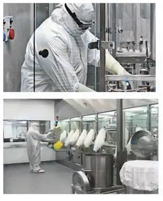
This regulatory emphasis requires QA & RA teams to ensure:
Documented expectations of airflow profiles
including homogeneity, validated velocity, and continuous sweeping across critical points.
Scientific justification for how airflow reforms after encounters with equipment
diffusers, baffles, lighting, VHP nozzles, sensors, and mechanical structures.
Evidence that interruptions do not compromise First Air at Points of Filling (PoF)
especially in complex barrier systems and during operator interventions.
Why First Air Matters for Regulatory Compliance
Annex 1 reinforces a holistic contamination control philosophy:Every element of the aseptic ecosystem ? CCS, facility design, barrier technology, equipment layout, procedural controls, airflow characterisation, and operator technique ? must converge toward maintaining a clean, undisturbed, verified First Air path.
This aligns with global regulatory trends emphasising:
Quality by Design (QbD) in aseptic engineering
Lifecycle validation rather than point-in-time qualification
Objective, data-driven risk assessment
Enhanced process visualisation (airflow & human factors)
For QA/RA functions, this means audits, inspections, and dossier submissions must clearly demonstrate how First Air is achieved, maintained, and assured over time.
Airflow Visualisation: A Regulatory Hot Button
Annex 1 elevates airflow visualisation (smoke studies) from ?good practice to a critical validation requirement.
Key expectations include:
1?? Defining Acceptance Criteria Upfront
The acceptance criteria must be scientifically justified and aligned with expected airflow profiles, not subjective post-review judgements.
2?? Visualising All Relevant Process States
Setup Routine operation Inherent interventions Corrective interventions
This ensures airflow protection is validated where the risk is highest.
3?? Demonstrating Airflow Recovery and Reformation
Particularly where equipment geometry creates unavoidable disturbances.
4?? Ensuring No Re-entrainment Above Critical Zones
Once protective airflow passes the PoF or open sterile containers, it must not be pulled back into the UDAF zone.
For QA reviewers and regulatory submitters, these documented studies serve as primary evidence of contamination control integrity.
Barrier Systems: Two UDAF Zones, One Compliance Goal
Inside RABS/isolators, Annex 1 prompts QA teams to consider the interplay of:
Zone 1: UDAF above equipment
Zone 2: UDAF interacting with complex equipment surfaces
As airflow shifts direction or velocity within these zones, the risk of turbulence increases - and with it, the burden of proof on First Air protection.
This is where aerodynamic design, URS requirements, and lifecycle smoke study programmes become crucial.
The QA/Reg Perspective: What Annex 1 Is Really Asking Us To Do
Move from conceptual First Air understanding to a documented, validated, risk-based assurance model
Provide regulators with visual, measurable, reproducible evidence of airflow performance
Ensure that interruptions closest to the PoF are thoroughly assessed and mitigated
Strengthen CCS narratives with detailed airflow logic
Translate airflow science into compliance-ready documentation
Annex 1 asks QA & Regulatory leaders not only to verify compliance ? but to own the scientific story of airflow protection.
FIRST AIR CONCEPT
Annex 1 and "First Air": What is it and how is it used?
First Air as a concept is a major update in the new Annex 1 to continue global harmonisation of regulatory standards, but what is it and how is it used in the new document to improve clarity and compliance?
The regulatory expectations of the protective airflow First Air are defined in Annex 1 Glossary; "First Air ? Refers to filtered air that has not been interrupted prior to contacting exposed product and product contact surfaces with the potential to add contamination to the air prior to reaching the critical zone??
One of the important points of emphasis in the revised Annex 1 is the regulatory codification of air handling guidelines and parameters, including the First Air principle.
When critical zones are accounted for and prioritised in the design and execution of sterile production processes, then the safety and quality of the product is a repeatable, expected outcome.
First Air is defined generally as uninterrupted unidirectional filtered airflow?
First Air as a concept is specified in name or function by multiple regulatory bodies and pharmaceutical organisations, including USP, PDA, ISO, and the FDA, amongst others, and its inclusion in the revised Annex 1 is evidence of the continuing global harmonisation of standards across regulatory bodies. But how does unidirectional airflow interact with a critical zone from an operational point of view?
First Air speaks to the quality necessary to protect a product and maintain the integrity of a critical zone, and unidirectional airflow is the mechanism by which that happens. Annex 1 specifies that the airflow should be homogenous and sweep away from the product continuously at a specified and validated velocity.
Originating as a principle of product protection during manual aseptic manipulations, First Air has long been considered necessary to maintain Grade A air over exposed and unsealed sterile products.
Annex 1 offers insight into how operators can ensure First Air remains at its most effective and uninterrupted over critical zones?
In reality, HEPA filtered airflow supply will be "interrupted prior to contacting exposed product and product contact surfaces via contact with Air diffusers and support frames, lighting above the air diffusers, VHP/ vH202 injection nozzles (if applied) and air flow velocity sensors. Any such interruptions should not be impactful to First air protection, meaning air that passes over such surfaces should reform and exhibit unidirectional airflow characteristics when applied at critical points that require airflow protection.
First Air commences at the exit of the HEPA filtered air flow supply and enroute to provide First air protection the airflow should not pass over surfaces that provide extraneous particulate and microbial contamination to the protective airflow e.g. they are not particle shedding surfaces and are subjected to a bio-decontaminated/ disinfection process and afterwards are not open to re-contamination.
First air should not be compromised via disruptive influences that impact First Air protection.
Importantly in any airflow visualisation of protective airflows once the UDAF supply including "First Air from a HEPA filtered source has passed the critical point of First air protection any turbulences (non-UDAF) and airflow below that potentially may include additional particulate concentration levels as a result of entrainment from surfaces subject to particulate settlement must not re-introduce into the First Air protection. The protective First Air after passing over the Point of Filling (PoF) and open product containers of sterile product should not re-introduce into the UDAF protective First air above the open containers.
The Air velocity profiles
Inside a barrier system there are two UDAF zones that work together to characterise protective airflow. The initial part of protective airflow is above any installed process equipment hence not subjected to significant adverse airflow disruptions. Once the airflow enters into the zone with process equipment with complex surface profiles there are resultant changes of airflow direction and changes in the velocity profile.
Airflow visualisation studies and characterisation of profile.
When airflow visualisation study protocols are developed it is important to define expectations of what the protective airflow should look like and where turbulences are expected and considered acceptable e.g. not impacting First Air protection.
Such a definition of expected airflow profiles becomes the acceptance criterion in smoke study protocols to mitigate against subjectivity in assessing smoke study videos as to what is and is not acceptable.
Execution of airflow visualisation needs to be considered in all process stages when protective airflow is required, including set-up (with open barrier doors) in operations and for any inherent and corrective interventions.
The type of smoke generator and integration of smoke supply and distribution and associated camera locations that present the airflow profile as videos for review needs to be part of the airflow visualisation study design.
The holistic approach outlined in Annex 1 invokes an important point: The entirety of the aseptic processing programme should work towards the single goal of the safe, repeatable aseptic production of a product.
The CCS, process design, and technology should all work to support the integrity of critical zones and the efficacy of First-Air defence.
In actual real-world settings, then, how can operators ensure First Air remains at its most effective and uninterrupted over critical zones Here, Annex 1 also offers insight.
Critical zone operations: Key considerations
Airflow visualisation is a significant point of emphasis in the revised Annex 1 and functions both as a quality-by-design tool and a necessary means of validation for air pressure, air velocity, and airflow quality, amongst other aspects of a system and the larger operation.
Definition of First Air protection and clarity
The regulatory expectations of the protective airflow First Air are defined in Annex 1 Glossary; "First Air ? Refers to filtered air that has not been interrupted prior to contacting exposed product and product contact surfaces with the potential to add contamination to the air prior to reaching the critical zone??
In reality, HEPA filtered airflow supply will be "interrupted prior to contacting exposed product and product contact surfaces via contact with Air diffusers and support frames, lighting above the air diffusers, VHP/ vH202 injection nozzles (if applied) and air flow velocity sensors. Any such interruptions should not be impactful to First air protection, meaning air that passes over such surfaces should reform and exhibit unidirectional airflow characteristics when applied at critical points that require airflow protection.
First Air commences at the exit of the HEPA filtered air flow supply and enroute to provide First air protection the airflow should not pass over surfaces that provide extraneous particulate and microbial contamination to the protective airflow e.g. they are not particle shedding surfaces and are subjected to a bio-decontaminated/ disinfection process and afterwards are not open to re-contamination.
First air should not be compromised via disruptive influences that impact First Air protection.
Importantly in any airflow visualisation of protective airflows once the UDAF supply including "First Air from a HEPA filtered source has passed the critical point of First air protection any turbulences (non-UDAF) and airflow below that potentially may include additional particulate concentration levels as a result of entrainment from surfaces subject to particulate settlement must not re-introduce into the First Air protection. The protective First Air after passing over the Point of Filling (PoF) and open product containers of sterile product should not re-introduce into the UDAF protective First air above the open containers.
The Air velocity profiles
Inside a barrier system there are two UDAF zones that work together to characterise protective airflow. The initial part of protective airflow is above any installed process equipment hence not subjected to significant adverse airflow disruptions. Once the airflow enters into the zone with process equipment with complex surface profiles there are resultant changes of airflow direction and changes in the velocity profile.
Some airflows will speed up over surfaces and may slow down afterwards as airflow changes direction. Importantly the airflow velocity qualifications (measurements e.g. 0.45m/s +/- 20%) should apply within the UDAF zone above process equipment so disruptive airflows do not confuse air velocity results. Once the protective airflow flows over process equipment the focus moves to uni-directional airflow patterns with less focus on specific air velocity values.
Airflow visualisation studies and characterisation of profile.
When airflow visualisation study protocols are developed it is important to define expectations of what the protective airflow should look like and where turbulences are expected and considered acceptable e.g. not impacting First Air protection.
Such a definition of expected airflow profiles becomes the acceptance criterion in smoke study protocols to mitigate against subjectivity in assessing smoke study videos as to what is and is not acceptable.
Execution of airflow visualisation needs to be considered in all process stages when protective airflow is required, including set-up (with open barrier doors) in operations and for any inherent and corrective interventions.
The type of smoke generator and integration of smoke supply and distribution and associated camera locations that present the airflow profile as videos for review needs to be part of the airflow visualisation study design.
As a formal qualification requirement airflow visualisation should not be considered as an R&D study with ?make do integration that can compromise at rest and in-operation studies of operational process equipment and operator interactions in processing.
As smoke studies are a ?contaminating event the execution of formal qualification smoke studies should follow environmental control Classification (to ISO14644-1) where (IQOQ) qualified equipment can be run and studies completed without risk of subsequent environmental control setting changes that may impact protective airflow patterns.
Classification is focused around particles only and the ability of the air handling and filtration systems to meet the air cleanliness levels and clean up rates with at rest and in-operation studies completed.
Classification applies before formal Environmental Qualification (to Annex1) where both total particulate and microbial conditions in are established and qualified ahead of APS: Aseptic Process Simulations. Smoke studies are likely to combine different methods of smoke distribution so ?mass smoke? (with technical integration for supply and distribution) can be used to assess airflow patterns and airflow cascades together and more targeted studies with handheld smoke generation devices at localised points of identified risk where First air protection is required.
Summary and future perspective
The closer to the point of protection where First Air applies where airflow interruptions occur e.g. airflow passing over parts of process equipment the more the risks are of impactful turbulences that may compromise First Air protection, hence aerodynamic design matters in such (and all) critical localities.
Robotics have great benefits but design integration needs to be considered in respect of interaction with First Air protection, so benefits are not compromised by adding risks that result in loss of protective airflow. No process is free of contamination risks and although technologies may mitigate risks the integration into a process must follow QRM and QbD principles.
The impact of Annex 1 revision on the aspect of protective airflow is therefore impacting all stakeholders where improvements are considered to be required in aerodynamic design, Airflow visualisation study design and Smoke study execution.
One of the next areas of study in protective airflow will be in environmental monitoring systems and their interaction and detectability at critical process points where First Air protection applies. Continuous Total particle and microbial monitoring is required in Grade A Aseptic processing zones.
It will be necessary to detect when contamination is entering into a critical process point of First air protection and/or there is loss of protection (First air interruption) opening the product and product contact surfaces to risk of airborne contamination.
FIRST AIR CONCEPT FINAL
Annex 1 and "First Air": What is it and how is it used?
First Air as a concept is a major update in the new Annex 1 to continue global harmonisation of regulatory standards, but what is it and how is it used in the new document to improve clarity and compliance?
The regulatory expectations of the protective airflow First Air are defined in Annex 1 Glossary; "First Air ? Refers to filtered air that has not been interrupted prior to contacting exposed product and product contact surfaces with the potential to add contamination to the air prior to reaching the critical zone??
One of the important points of emphasis in the revised Annex 1 is the regulatory codification of air handling guidelines and parameters, including the First Air principle.
When critical zones are accounted for and prioritised in the design and execution of sterile production processes, then the safety and quality of the product is a repeatable, expected outcome.
First Air is defined generally as uninterrupted unidirectional filtered airflow?
First Air as a concept is specified in name or function by multiple regulatory bodies and pharmaceutical organisations, including USP, PDA, ISO, and the FDA, amongst others, and its inclusion in the revised Annex 1 is evidence of the continuing global harmonisation of standards across regulatory bodies. But how does unidirectional airflow interact with a critical zone from an operational point of view?
First Air speaks to the quality necessary to protect a product and maintain the integrity of a critical zone, and unidirectional airflow is the mechanism by which that happens. Annex 1 specifies that the airflow should be homogenous and sweep away from the product continuously at a specified and validated velocity.
Originating as a principle of product protection during manual aseptic manipulations, First Air has long been considered necessary to maintain Grade A air over exposed and unsealed sterile products.
Annex 1 offers insight into how operators can ensure First Air remains at its most effective and uninterrupted over critical zones?
In reality, HEPA filtered airflow supply will be "interrupted prior to contacting exposed product and product contact surfaces via contact with Air diffusers and support frames, lighting above the air diffusers, VHP/ vH202 injection nozzles (if applied) and air flow velocity sensors. Any such interruptions should not be impactful to First air protection, meaning air that passes over such surfaces should reform and exhibit unidirectional airflow characteristics when applied at critical points that require airflow protection.
First Air commences at the exit of the HEPA filtered air flow supply and enroute to provide First air protection the airflow should not pass over surfaces that provide extraneous particulate and microbial contamination to the protective airflow e.g. they are not particle shedding surfaces and are subjected to a bio-decontaminated/ disinfection process and afterwards are not open to re-contamination.
First air should not be compromised via disruptive influences that impact First Air protection.
Importantly in any airflow visualisation of protective airflows once the UDAF supply including "First Air from a HEPA filtered source has passed the critical point of First air protection any turbulences (non-UDAF) and airflow below that potentially may include additional particulate concentration levels as a result of entrainment from surfaces subject to particulate settlement must not re-introduce into the First Air protection. The protective First Air after passing over the Point of Filling (PoF) and open product containers of sterile product should not re-introduce into the UDAF protective First air above the open containers.
The Air velocity profiles
Inside a barrier system there are two UDAF zones that work together to characterise protective airflow. The initial part of protective airflow is above any installed process equipment hence not subjected to significant adverse airflow disruptions. Once the airflow enters into the zone with process equipment with complex surface profiles there are resultant changes of airflow direction and changes in the velocity profile.
Airflow visualisation studies and characterisation of profile.
When airflow visualisation study protocols are developed it is important to define expectations of what the protective airflow should look like and where turbulences are expected and considered acceptable e.g. not impacting First Air protection.
Such a definition of expected airflow profiles becomes the acceptance criterion in smoke study protocols to mitigate against subjectivity in assessing smoke study videos as to what is and is not acceptable.
Execution of airflow visualisation needs to be considered in all process stages when protective airflow is required, including set-up (with open barrier doors) in operations and for any inherent and corrective interventions.
The holistic approach outlined in Annex 1 invokes an important point: The entirety of the aseptic processing programme should work towards the single goal of the safe, repeatable aseptic production of a product.
The CCS, process design, and technology should all work to support the integrity of critical zones and the efficacy of First-Air defence.
In actual real-world settings, then, how can operators ensure First Air remains at its most effective and uninterrupted over critical zones Here, Annex 1 also offers insight.
Critical zone operations: Key considerations
Airflow visualisation is a significant point of emphasis in the revised Annex 1 and functions both as a quality-by-design tool and a necessary means of validation for air pressure, air velocity, and airflow quality, amongst other aspects of a system and the larger operation.
The impact of Annex 1 revision on the aspect of protective airflow is therefore impacting all stakeholders where improvements are considered to be required in aerodynamic design, Airflow visualisation study design and Smoke study execution.
Summary and future perspective
The closer to the point of protection where First Air applies where airflow interruptions occur e.g. airflow passing over parts of process equipment the more the risks are of impactful turbulences that may compromise First Air protection; hence Air flow visualization study design and smoke study execution matters in all critical localities.
Regulatory auditors views dynamic smoke studies as an integral part of the overall sterility-assurance system. Their effectiveness is closely linked to cleanroom design, equipment layout, barrier configuration, operator behaviour, intervention control, environmental monitoring, and aseptic process validation. A scientifically meaningful smoke study should demonstrate protection of critical processing zones under realistic operating conditions rather than simply confirming that air is moving within a controlled environment.
•SANTHOSHA M K
•Senior Manager - Validations
•INCEPBIO
•Cleanroom and HVAC Validation Expertise
•Driving Growth and Quality Excellence through CQV
•Pharma Consulting and Training for Industry Best Practices
•Trainer
•Optimizing Smoke Studies for Compliance and Safety
•Ensuring Regulatory Compliance
•Safeguarding Quality Assurance
•Enhancing Data Integrity
•Safeguarding Patient Safety
•Containment and Control
•Importance of Air Flow Visualization
•Definition and Purpose: A smoke study, or air flow pattern visualization study, is a method used to observe and understand how air moves within clean rooms and isolators. This process is fundamental for assessing the effectiveness of containment and control measures
•The study allows us to visualize the direction and speed of air currents in controlled environments, providing crucial insights into the efficiency of air handling systems.
•The primary objective is to evaluate the efficiency of air flow systems in controlling contamination and preventing the spread of particulates.
•Basics of Air Flow Visualization
•The cleanroom fogger that generates a fog or smoke from water vapor using water for injection (WFI) or deionized water is recommended.
•Methods for generating the water vapor fog include megasonic vaporization, steam (liquid nitrogen), and dry ice.
Equipment and Support
Types of Smoke Used:
•Glycol-Based Smoke: Commonly used in pharmaceutical environments for its visibility and safety, but they leave residues.
•Oil-Based Smoke: Used in various industrial settings for its persistence and detectability, Produces a visible and lingering smoke.
•Contamination risk is high.
•Water-Based Smoke: Suitable for certain applications where other substances may not be appropriate.
•Generates a mist or fog, providing a visible but lighter form of smoke.
•Suitable for situations where the use of other substances might not be appropriate, such as in cleanrooms with sensitive equipment.
•Contaminant Introduction: The introduction of substances for smoke studies should not pose contamination risks to the clean room or isolator.
•Compatibility: The substance used should be compatible with the materials and surfaces within the controlled environment to prevent any adverse reactions.
•Residue Formation: Some substances may leave residues on surfaces. Residue can compromise the cleanliness of the environment and, in some cases, impact the quality of pharmaceutical products.
•Long-Term Residual Effects: Understanding the potential for long-term residual effects is crucial, especially if the substance could interact with ongoing manufacturing processes.
Continuedh3>
Points to be consider for the Smoke Study
Material Compatibility: Consideration should be given to the materials present in the clean room or isolator. The substance used should not react with or damage these materials.
Equipment Impact: The substance should not adversely affect the performance or integrity of sensitive equipment present in the clean room.
Worker Exposure: The substances chosen should not pose health risks to personnel involved in the study.
Safety Measures: Adequate safety measures, such as personal protective equipment (PPE), should be in place to mitigate any potential risks associated with the substances.
Impact on HVAC Systems:
•HVAC Efficiency: Certain substances may impact the efficiency of heating, ventilation, and air conditioning (HVAC) systems in the clean room.
•Air Filtration: The study should not compromise the effectiveness of air filtration systems, which are crucial for maintaining air quality.
•The purpose of the Air Flow Visualization test is to demonstrate that the airflow direction and its uniformity of velocity conform to the design and performance specifications. The airflow direction test can be conducted in the at-rest state to determine the basic cleanroom airflow patterns and can be repeated in the operational state simulating actual operations. ISO 14644-3:2019
•It should be demonstrated that air-flow patterns do not present a contamination risk, e.g. care should be taken to ensure that air flows do not distribute particles from a particle generating person, operation or machine to a zone of higher product risk. - EU GMP Annex 1: 2008
Filming the Smoke study
Reflections - To overcome this, the photographer should be aware of this phenomenon, and even film from a couple of different angles in order to present the actual airflow.
Starting At The Top - Be sure to capture the area where the HEPA-filtered air is introduced, commonly at the ceiling, and slowly pan down following the smoke direction as it flows toward work surfaces and equipment.
The smoke should be introduced with the nozzle pointed into the airstream. This will demonstrate that the room air supply is sufficient to carry the smoke in the direction of the airflow.
Use the zoom function of the camera to capture the area around the product path and pay attention particular to open product.
Panorama - An overview picture scanning the work area can help to orient the viewer as to where they are in the process.
There should be no turbulence or airflow bouncing off production equipment or any eddies (air moving in a circular pattern).
Smoke should wash over process equipment and product pathways smoothly in one direction then continue through the work area toward the floor.
Use caution when zooming in and out of the scene or quick camera movements that can cause confusion or a dizzy collection of scenes.
Remember the camera will ultimately be the eye of the viewer.
The air supply should continually wash the product-exposed area, equipment, and personnel.
Airflow should be unidirectional in nature and should show uniform flow patterns with minimum turbulence.
•Acceptance Criteria
•Date & Time stamp
•Production area / equipment name, Company Details
•Narration
•Confidentiality and data security
•Report Contents
•Equipment/ Instrument Qualification Approach In Pharmaceutical Industry
Qualification And Validation
OBJECTIVE
•Why Qualification and Validation required in Pharmaceutical industry?
•Safety, quality and efficacy are built into the product cannot be "inspected or tested into a product"
•What is the need for Validation?
•Need for confidence that the product will consistently meet predetermined specifications and attributes
•Assures Quality Regulatory Requirement Reduces Cost
•And most important is - Its the LAW!
•Consequences of NOT Validating Systems and Processes:span>
•Poor Product Quality, Bad Publicity, Death, Financial losses
•What to Qualify/ Validate:
•Test Methods, Facility, Systems, equipment, Processes, Premises
•Responsibility:
•Responsibility for qualification and validation is a multi-disciplinary including: Heads of Production and QC, Head of Engineering and Contractors/ suppliers.
WHAT IS VALIDATION?
WHAT IS QUALIFICATION?
•Validation is defined as the collection & evaluation of data, from the process design stage through commercial production, which establishes scientific evidence that a process is capable of consistently delivering quality product.
•Documenting that a process or system meets its pre-determined specifications and quality attributes
•Qualification is defined as the documented evidence that the subject equipment has been installed as per specification (manufacturer's recommendation) and will attain and maintain critical process parameters repeatedly and reliably.
•Performed to establish confidence that process equipment and ancillary systems are capable of consistently operating within established limits and tolerances.
•Comparison between Qualification and Validation
• Validation and Qualification are essentially components of the same concept.
• Qualification is normally used for equipment, utilities and systems
• Validation is normally used for processes and methods.
Qualification - Standard V Model
Design Qualification (DQ)
Installation Qualification (IQ)
Operational Qualification (OQ)
Performance Qualification (PQ)
•User Requirement Specification & Commissioning
•User Requirement Specification (URS)
•User Requirement Specification is a foundational document created by the end-user department to define the specific needs and functions of equipment, facilities, or systems.span>
•Commissioning
•Equipment start-up, adjustments, testing
•Ensures system is in a "State of Control"
•Supplements validity and compliance
•Conducted at manufacturer (FAT) or client (SAT) site
•Review and document design to meet quality requirements
•Confirms correct design and equipment selection
•Conducted before purchasing equipment
•DQ Process
•Collect market data on similar equipment
•Assess operational needs & available resources
•Evaluate space, maintenance, and operational requirements
•Final purchase decision
•Verifies installation matches design specifications
•Checks static attributes of facility/equipment
•Ensures proper documentation and compliance
•IQ Considerations
•Equipment design (materials, cleanability)
•Installation conditions (utilities, wiring, calibration)
•Supplier documents/manuals/software
•Environmental conditions (temperature, humidity)
•Spare parts and maintenance schedules
•Tests dynamic attributes under defined limits
•Confirms equipment works correctly under set parameters
•"Worst case" testing within proven acceptable range
•OQ Considerations
•Process control limits (time, temperature, pressure, speed)
•Software settings and material specifications
•SOPs and operator training
•Risk analysis & failure modes (FMEA, fault tree analysis)
•Also called process qualification
•Confirms consistent performance under real conditions
•Ensures product quality over time
•PQ Includes
•Uses actual product and processes defined in OQ
•Demonstrates process capability
•Confirms product acceptability
•Ensures long-term repeatability & stability
•Decommissioning
•Planned removal from operational use
•Confirms system was compliant at time of retirement
•Documentation of system status and conclusion
•Benefits of Validation & Qualification
•Compliance with regulatory requirements
•Improved product quality and safety
•Optimized processes and cost efficiency
•Risk reduction and better resource utilization
•Stronger market trust and competitiveness
•Conclusion
•Qualification/ Validation is essential for GMP compliance
•Ensures product quality, safety, efficacy
•Provides business benefits
•Lifecycle approach: structured, planned, documented
•Thank you..
What Is Moist Heat Sterilization?
Moist heat sterilization is the most established and widely accepted sterilization method in the pharmaceutical and biopharmaceutical industries. Where product formulation, materials, and container systems allow, it remains the preferred approach due to its proven effectiveness, reproducibility, and strong regulatory acceptance.
The Myth:
•Despite the long history, moist heat sterilization is still frequently misunderstood and oversimplified in GMP environments. In many organizations, moist heat sterilization is treated as synonymous with "autoclaving" and reduced to the routine use of a default cycle, typically 121°C for 15 minutes.
•This simplified view ignores that moist heat sterilization is not a single technology but a family of processes, each governed by distinct physical mechanisms, limitations, and risks. When these differences are not understood, inappropriate cycle selection, weak validation strategies, and avoidable GMP observations often follow.
•We are going to discuss, what is moist heat sterilization, how it works, and where it is applied in pharmaceutical manufacturing. It focuses on the fundamental principles, process types, and regulatory context needed to understand the technology without delving into cycle-selection logic or detailed validation strategies.
•Definition
•Moist heat sterilization is a process that inactivates microorganisms by applying heat in the presence of moisture, typically delivered as saturated steam or, in certain applications, as hot water under controlled pressure.span>
•In pharmaceutical GMP terms, the defining feature is not the heat source itself, but the presence of water in liquid or vapor form, which enables efficient heat transfer and rapid microbial inactivation.
•Scope of Moist Heat Sterilization
•Within pharmaceutical and biopharmaceutical manufacturing, moist heat sterilization is applied to a wide range of items, including:
•Terminal sterilization of aqueous medicinal products
•Sterilization of product-contact components and equipment
•Processing of hard goods, porous materials, and selected container systems
How Moist Heat Sterilization Works?
Moist heat sterilization relies on the presence of water, either as saturated steam or as hot liquid water, to efficiently transfer thermal energy to microorganisms. Water has significantly higher heat-transfer capacity than dry air; therefore, moist heat achieves microbial inactivation at lower temperatures and shorter exposure times than dry heat.
In steam-based systems, the critical event is condensation. When saturated steam contacts a cooler surface, it condenses into water, releasing latent heat. This rapid energy release causes an immediate, uniform increase in surface temperature, which is essential for effective microbial kill. In the absence of moisture, this mechanism does not occur, severely compromising sterilization effectiveness.
Steam Condensation and Latent Heat Transfer
Latent heat released during steam condensation is the dominant driver of lethality in moist heat sterilization. Unlike sensible heat (the temperature increase measured in air), latent heat releases a large amount of energy at constant temperature, making it highly efficient.
For this reason:
•Steam must physically contact the load surface
•Residual air must be minimized or eliminated
•Condensate must be allowed to drain to maintain continuous heat transfer
•Any condition that prevents condensation, such as trapped air, superheated steam, or inadequate circulation, reduces sterilization effectiveness, even if the chamber temperature appears correct.
Microbial Inactivation Mechanism
Moist heat inactivates microorganisms primarily by irreversibly denaturing proteins and enzymes essential to cellular metabolism and replication. This mechanism affects vegetative bacteria, fungi, and spores, with bacterial spores typically representing the most resistant challenge for moist heat processes.
The rate of inactivation depends on:
•Temperature at the microbial location
•Duration of exposure
•Moisture availability at the contact surface
•Because this mechanism is well understood and reproducible, moist heat sterilization is considered a robust and predictable process when physical conditions are controlled.
Sterility Assurance and Quantitative Lethality Concepts
Sterility assurance in pharmaceutical manufacturing is expressed probabilistically through the Sterility Assurance Level (SAL). For terminally sterilized medicinal products, an SAL of 10^-6 is typically expected, corresponding to a 1-in-1,000,000 probability of a non-sterile unit.
To quantify lethality, several interrelated parameters are used:
•D-value, which quantifies microbial resistance at a specific temperature
•z-value, which describes how microbial resistance changes with temperature
•F0which integrates time and temperature into a single cumulative lethality metric referenced to 121°C
•Parameter
•What It Describes
•What It Assumes
•Key Limitation
•D-value
•Microbial resistance at a given temperature
•Uniform exposure conditions
•Does not confirm steam contact
•z-value
•Temperature sensitivity of microbial death
•Predictable thermal response
•Independent of physical load effects
•F0
•Cumulative lethality referenced to 121°C
•Representative product temperature
•Can mask air removal or penetration failures
•SAL
•Probability of non-sterile unit
•Validated, controlled process
•Not measured directly per cycle
•These parameters are mathematical tools that describe microbial kill under defined conditions. They do not, by themselves, confirm that the required physical conditions, such as steam contact or uniform heating, were achieved throughout the load.
Physical Limitations That Affect Lethality
In practice, the effectiveness of moist heat sterilization is often limited by physical rather than microbiological factors. Common limitations include:
•Incomplete air removal, which blocks steam contact
•Non-uniform heat distribution within the chamber or load
•Load shielding and cold spot formation
•Inadequate condensate removal
•Packaging or container features that impede heat transfer
•These factors explain why identical time-temperature profiles can produce different outcomes depending on load configuration and process design. They also explain why calculated lethality must always be interpreted in the context of physical process performance.
Core Phases of a Moist Heat Sterilization Cycle
Although moist heat sterilization processes may differ in design and application, all steam- and water-based cycles follow a defined sequence of phases. Each phase has a specific function and directly influences sterility assurance, product quality, and container integrity.p>
•Conditioning and Air Removal Phase
•Heating (Come-Up) Phase
•Exposure (Holding) Phase
•Exhaust, Depressurization, and Drying Phase
•Cooling and Pressure Control Phase
•Understanding the different phases is essential for interpreting cycle performance and identifying potential risks.
•1. Conditioning and Air Removal Phase
•The conditioning phase prepares the load for effective sterilization by removing air and establishing the correct thermal environment. In steam-based systems, this is achieved through gravity displacement, active vacuum pulses, or a combination of both.
•Air is the primary antagonist of moist heat sterilization. If air remains trapped within the chamber or load, steam cannot contact critical surfaces, condensation does not occur, and heat transfer does not occur.
•(Conditioning and Air Removal Phase)
•This results in cold spots that may not reach sterilizing conditions, even when the chamber temperature appears acceptable.
•The effectiveness of this phase depends on:
•The air removal method employed
•Load geometry and porosity
•Packaging materials and drainage characteristics
•Failure in the conditioning phase compromises the entire sterilization process and cannot be compensated for by simply extending exposure time.
•2. Heating (Come-Up) Phase
•During the heating phase, the load temperature increases toward the target sterilization temperature. This phase is influenced by the load's thermal mass, the rate of steam or water delivery, and the heat-transfer efficiency.
•In steam cycles, heating occurs as steam condenses on cooler surfaces. In hot-water systems, heating occurs through direct contact with circulating water. The heating profile is particularly important for liquid loads and sealed containers, where internal temperatures may lag significantly behind chamber conditions.
•(Heating (Come-Up) Phase)
•Uneven or excessively rapid heating can introduce risks, including:
•Delayed heating at cold spots
•Pressure differentials affecting container integrity
•Localized overheating or boiling in liquid products
•3. Exposure (Holding) Phase
•The exposure phase is the period during which sterilizing conditions are intentionally maintained to deliver the required microbial lethality. Traditionally, this phase is defined by a specified temperature and time, but its effectiveness depends on conditions established in earlier phases.
•For exposure to be meaningful:
•All critical locations must already be at sterilizing temperature
•Steam or water contact must be maintained
•Pressure conditions must remain within validated limits
•(Exposure (Holding) Phase)
•The exposure phase does not correct deficiencies in air removal or heat transfer. Its role is to maintain lethality once the proper physical conditions are met.
•4. Exhaust, Depressurization, and Drying Phase
•Following exposure, the sterilization medium is removed, and the system transitions toward ambient conditions. In steam cycles, this involves exhaust & where applicable, vacuum drying. In water-based systems, controlled drainage & pressure reduction are used.
•This phase is critical for:
•Preventing excessive condensate retention
•Avoiding recontamination or moisture-related quality issues
•Protecting container closure systems from stress
•Poorly controlled exhaust or drying can result in wet loads, container deformation, or compromised package integrity, all of which have GMP implications.
•5. Cooling and Pressure Control Phase
•Cooling brings the load to a safe handling temperature and stabilizes the system. For sealed liquid products, cooling must be carefully controlled to prevent internal overpressure or vacuum formation, which could damage containers or compromise closure integrity.
•In processes such as steam-air mixture or superheated hot-water systems, pressure is actively controlled during cooling to balance internal and external forces acting on the container. Inadequate control during this phase can render an otherwise successful sterilization process ineffective.
•Types of Moist Heat Sterilization Processes Used in the Pharmaceutical Industry
•Moist heat sterilization is not a single, uniform process. It encompasses a range of technologies that differ in how heat and moisture are delivered, how pressure is controlled, and which physical risks dominate. Regulatory frameworks explicitly recognize these differences, and GMP compliance depends on applying each process within its intended scope of use.
Types of Moist Heat Sterilization in Pharma Industry
•Gravity Displacement Steam Sterilization
•Gravity displacement cycles rely on the natural tendency of steam to displace air downward and out of the chamber. Because air removal is passive, these cycles have limited capability to eliminate residual air from complex or porous loads.
Typical applications include:
•Unwrapped metal instruments
•Simple glassware
•Loads with minimal internal voids or shielding
•The primary limitation is air entrapment, which can prevent steam from contacting all load surfaces. As a result, these cycles are limited to simple, non-porous items and are unsuitable for wrapped, porous, or hollow loads.
•Pre-Vacuum (Porous Load) Steam Sterilization
•Pre-vacuum cycles actively remove air using one or more vacuum pulses prior to steam exposure. This design enables effective steam penetration into porous materials and complex geometries.
•Textiles and gowning
•Filters and stopper bags
•Tubing, hoses, and hollow or layered components
•These cycles are specifically engineered to address air removal and steam penetration challenges. They represent the standard approach for porous and hollow loads in GMP environments. Their effectiveness depends on robust vacuum performance, proper load configuration, and reliable steam quality.
•Saturated Steam Liquid Sterilization Cycles
•Liquid cycles are used for aqueous products sterilized in open or vented containers. In these processes, sterilization effectiveness is governed by heat transfer into the liquid, rather than by steam penetration into a porous structure.
•Aqueous products in open or loosely vented containers
•Liquids requiring controlled exhaust to prevent boil-over
•Because the liquid itself heats more slowly than the chamber environment, internal product temperature is the critical determinant of lethality. Chamber temperature alone does not represent sterilization conditions for these loads.
•SteamAir Mixture (SAM) Processes
•SAM processes combine steam with controlled amounts of air, allowing independent control of temperature and pressure. This makes them suitable for sealed containers that would otherwise be damaged by pressure differentials in saturated steam cycles.
•Pre-filled syringes
•Blow-Fill-Seal (BFS) and Form-Fill-Seal (FFS) containers
•Flexible or semi-rigid sealed containers
•In SAM processes, both heat transfer and container integrity are critical. Pressure is deliberately managed during heating and cooling to protect the container while still achieving sterilizing conditions.
•Superheated Hot-Water Shower / Cascade Processes
•Superheated hot-water systems deliver heat through direct contact with circulating water under controlled pressure. Unlike steam cycles, wet loads are acceptable because the products are terminally sealed before sterilization.
•Sealed aqueous products in rigid containers
•Large-volume parenterals (LVPs)
•Ampoules and similar formats
•(Superheated Hot-Water Shower / Cascade Processesspan>
•These systems offer highly uniform heat transfer and excellent pressure control, making them well-suited for heat-sensitive formulations or containers requiring counter-pressure protection. Effective drainage, water distribution, and temperature uniformity are essential to their performance.
•Process/ Technology
•Moisture Present
•Primary Mechanism
•Typical GMP Use
•Saturated steam (autoclave)
Yes (steam)
•Condensation & latent heat
•Equipment, components, hard goods
•Pre-vacuum steam
•Steam penetration after air removal
•Porous and hollow loads
•Steamair mixture (SAM)
•Yes (steam + air)
•Controlled heat + pressure
•Sealed containers, PFS, BFS
•Superheated hot-water systems
•Yes (liquid water)
•Direct water heat transfer
•LVPs, sealed aqueous products
What Determines Whether a Load Is Easy or Difficult to Sterilize
Not all items respond to moist heat sterilization in the same way. Even when the same sterilizer and nominal cycle parameters are used, the physical characteristics of the load can dramatically influence sterilization effectiveness. From a GMP perspective, this is one of the most frequently underestimated aspects of moist heat sterilization.
The difficulty of sterilizing a load is primarily driven by how readily moist heat can reach, transfer energy to, and uniformly condition all critical locations within it.
•Geometry and Internal Complexity
•Simple, solid items with smooth external surfaces are generally easier to sterilize than loads with complex internal features. Hollow components, narrow lumens, bends, dead legs, layered assemblies can trap air and restrict contact between steam or water.
•Examples of higher-risk geometries include:
•Long or narrow tubing/ Filters and stopper bags
•Nested or stacked components
•Multi-part assemblies with internal voids
•As internal complexity increases, the risk that certain locations will experience delayed heating or incomplete exposure to moist heat increases.
•Porosity and Air Retention
•Porous materials, such as textiles, filters, or wrapped components, can retain significant volumes of air. This retained air must be effectively removed during the conditioning phase to allow steam penetration.
•If air removal is incomplete:
•Steam cannot condense uniformly
•Heat transfer is impaired
•Cold spots may persist despite acceptable chamber conditions
•Porosity, therefore, represents a fundamental challenge for moist heat processes and requires appropriate cycle design and load configuration.
•Load Mass and Thermal Inertia
•Large or densely packed loads absorb heat more slowly than light or loosely arranged loads. High thermal mass can delay temperature equilibration and shift the cold spot deeper into the load.
•Factors that increase thermal inertia include:
•Heavy metal components
•High fill volumes of liquid products
•Dense stacking or close packing
•If not properly accounted for, thermal inertia can result in insufficient lethality at the most difficult-to-heat locations.
•Packaging and Wrapping Materials
•Packaging materials influence both air removal and heat transfer. Wraps, pouches, trays, and containers can act as barriers if they are not compatible with the selected sterilization process.
•Key considerations include:
•Steam permeability of wraps
•Drainage capability of trays and containers
•Resistance of packaging to deformation or collapse
•Packaging that performs well in one cycle type may behave poorly in another, reinforcing the need for process-specific justification.
•Drainage and Condensate Management
•Effective drainage is essential for maintaining continuous heat transfer during steam sterilization. Accumulated condensate can shield surfaces, cool local areas, and interfere with sterilization.
•Poor drainage may result from:
•Flat or enclosed surfaces
•Improper load orientation
•Overloaded trays or baskets
•Loads that do not drain effectively are inherently more difficult to sterilize and require careful consideration during process design.
Validation & Routine Control: A High-Level Overview
•Purpose of Validation in Moist Heat Sterilization
•Validation establishes documented evidence that a moist heat sterilization process can reliably achieve the required level of sterility under defined worst-case conditions. It is not intended to repeatedly prove sterility, but to demonstrate that the process design, parameters, and controls are fundamentally sound.
•In practical terms, validation addresses:
•Whether the selected sterilization process can control the dominant physical risks
•Where the coldest or most difficult-to-sterilize locations are
•Whether process parameters consistently achieve the intended lethality
•Validation is therefore a one-time (or infrequent) demonstration of capability, performed under carefully designed and challenged conditions.
•Lifecycle Approach to Validation
•Modern GMP expectations frame sterilization validation as a lifecycle activity rather than a single event. This includes:
•Installation Qualification (IQ):Â confirming the sterilizer and utilities are installed correctly
•Operational Qualification (OQ):Â verifying control of temperature, pressure, air removal, alarms, and safety systems
•Performance Qualification (PQ):Â demonstrating effective sterilization of representative worst-case loads
•This lifecycle approach ensures that sterilization capability is not assumed based solely on equipment but is demonstrated in the context of real loads and operating conditions.
•Role of Mapping and Penetration Studies
•Mapping and penetration studies are tools used during validation to understand process behaviour. Their purpose is to identify the temperature distribution, heat-transfer characteristics, and locations where sterilization is most difficult to achieve.
•These studies do not define routine acceptance criteria. Instead, they provide the scientific basis for:
•Selecting critical process parameters
•Defining acceptable operating ranges
•Establishing routine monitoring points
•Once validation is complete, these studies are not repeated on a batch-by-batch basis.
•Routine Control and Batch Release
•Routine control confirms that each sterilization cycle is executed within the validated state. It focuses on verifying that critical process parameters remain within predefined limits and that no events occurred that could compromise sterility assurance.
•Routine batch release typically involves:
•Review of critical cycle parameters
•Confirmation of alarms and deviations
•Verification of adherence to validated load configuration
•Importantly, routine release does not repeat validation activities or re-establish worst-case conditions.
Key Regulatory Guidelines Governing Moist Heat Sterilization
Moist heat sterilization in the pharmaceutical industry is governed by a network of harmonised regulatory guidelines and international standards. These documents do not prescribe fixed cycle parameters; rather, they collectively establish expectations for process selection, validation, control, and documentation, grounded in scientific understanding and risk management.
•EU GMP Annex 1 (2022): Manufacture of Sterile Medicinal Products
•EU GMP Annex 1 is the most influential regulatory document shaping current expectations for moist heat sterilization in Europe and globally.
•Key principles relevant to moist heat sterilization include:
•Moist heat sterilization is not limited to saturated steam; alternative systems such as steam-air mixtures and superheated hot-water systems are explicitly permitted when justified.
•Sterilization processes must be appropriate for the load and container system, rather than selected by default
•Effective air removal and steam penetration must be assured and routinely verified for porous and hard-goods loads.
•For fluid sterilization, temperature, time, and/or F0may be used as acceptance criteria, recognizing heat transfer as the governing mechanism.
•Heat-sensitive or non-rigid containers must be protected through pressure control and controlled heating/cooling rates.
•Alternative moist-heat systems require enhanced validation, including full-load temperature mapping and demonstration of uniformity and reproducibility.
•Annex 1 clearly positions moist heat sterilization as a risk-based, mechanism-dependent process and embeds it within the Contamination Control Strategy (CCS).
•EMA Guideline on the Sterilisation of the Medicinal Product, Active Substance, Excipient and Primary Container
•The EMA guideline complements Annex 1 by providing more detailed expectations for terminal sterilization and post-aseptic heat treatment.
•Key regulatory clarifications include:
•Differentiation between:
•Reference and overkill terminal steam sterilization cycles
•Reduced lethality cycles (F0 8 minutes), which require increased validation effort
•Post-aseptic terminal heat treatment (F0< 8 minutes), which is not equivalent to terminal sterilization
•Explicit linkage between bioburden assumptions, delivered lethality, and validation depth
•Clear expectations for dossier justification when non-standard sterilization approaches are applied
•This guideline underscores that not all steam-based processes provide equivalent sterility assurance, and that validation and control strategies must reflect the chosen approach.
•ISO 17665: Sterilization of Health Care Products - Moist Heat
•ISO 17665 provides the international standard framework for the development, validation, and routine control of moist heat sterilization processes.
•Key ISO principles include:
•Sterilization processes must be selected based on product and load characteristics, not equipment capability alone.
•Validation and routine control must reflect the actual sterilization mechanism (air removal, steam penetration, heat transfer).
•Lethality metrics such as F0should be applied only where meaningful measurements of product temperature are possible.
•A lifecycle approach is required that covers development, qualification, routine control, and requalification.
•ISO 17665Â strongly supports the risk-based, load-specific expectations articulated in Annex 1.
•PDA Technical Reports (Supporting Industry Guidance)
•While not regulatory documents, PDA Technical Reports are frequently referenced during inspections as state-of-the-art industry guidance.
•PDA TR-1: Validation of Moist Heat Sterilization Processes
•PDA TR-48: Moist Heat Sterilization of Aqueous Liquids
•These reports provide practical interpretations of regulatory and ISO requirements, particularly for air removal testing, load configuration, the use of biological indicators, and temperature mapping strategies.
•Conclusion
•Moist heat sterilization remains one of the most powerful and reliable sterilization methods available to the pharmaceutical industry, but only when it is applied with scientific understanding, process awareness, and risk-based control.span>
•Moist heat sterilization encompasses multiple technologies, each governed by different physical mechanisms, limitations, and risks.
•Regulatory expectations have clearly evolved. Authorities no longer assess sterilization solely by whether a cycle reached a predefined temperature for a set time. They evaluate whether manufacturers understand how and why sterility is achieved for a given load, container system, and process design, and whether this understanding is consistently reflected in validation, routine control, and documentation.
Introduction
In the pharmaceutical industry, quality is directly connected to patient safety. Medicines must consistently meet defined standards of identity, strength, purity, safety, efficacy, and quality throughout their lifecycle. A failure in a pharmaceutical quality system can have consequences far beyond financial loss or customer dissatisfactionâ€â€it can potentially affect patient health and safety.
For this reason, pharmaceutical organizations require a robust and well-integrated Pharmaceutical Quality Management System (PQMS) to ensure that products are consistently manufactured, tested, stored, distributed, and controlled in accordance with applicable regulatory requirements and current Good Manufacturing Practices (cGMP).
A pharmaceutical Quality Management System is not simply a set of procedures maintained by the Quality Assurance Department. It is a company-wide framework that integrates Quality, Regulatory compliance, Risk management, Operations, Laboratory controls, Supply chain, Engineering, Validation, and continual improvement.
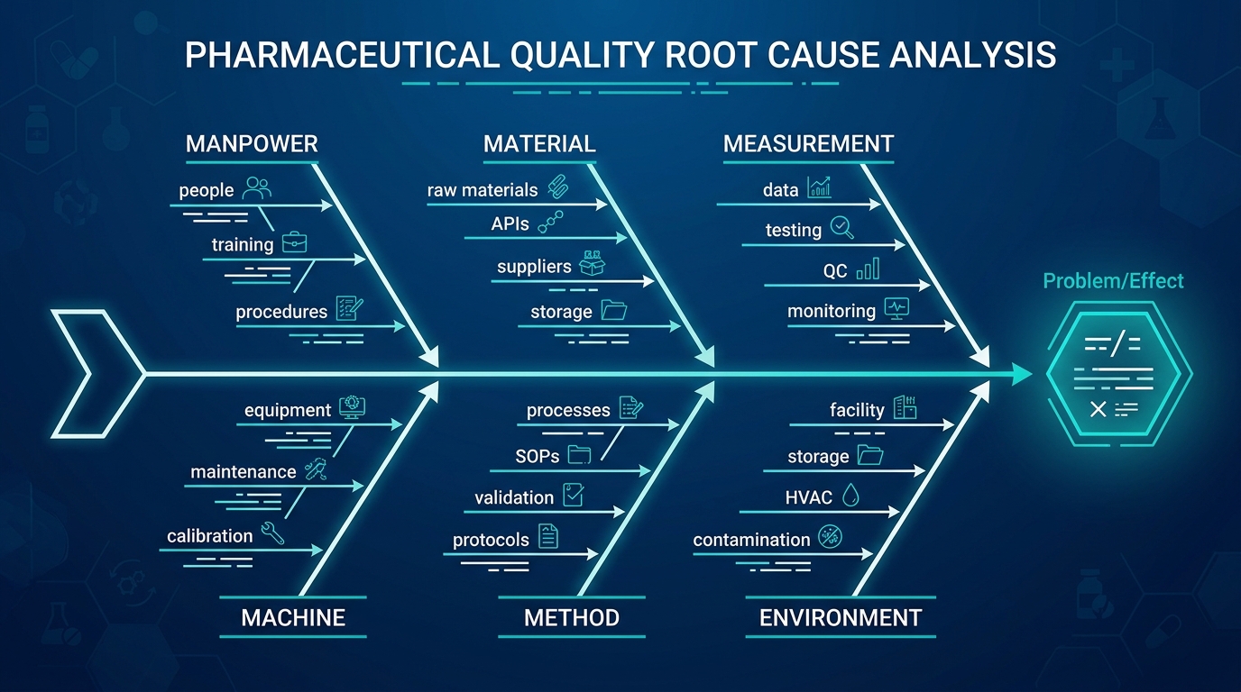
What Is a Pharmaceutical Quality Management System?
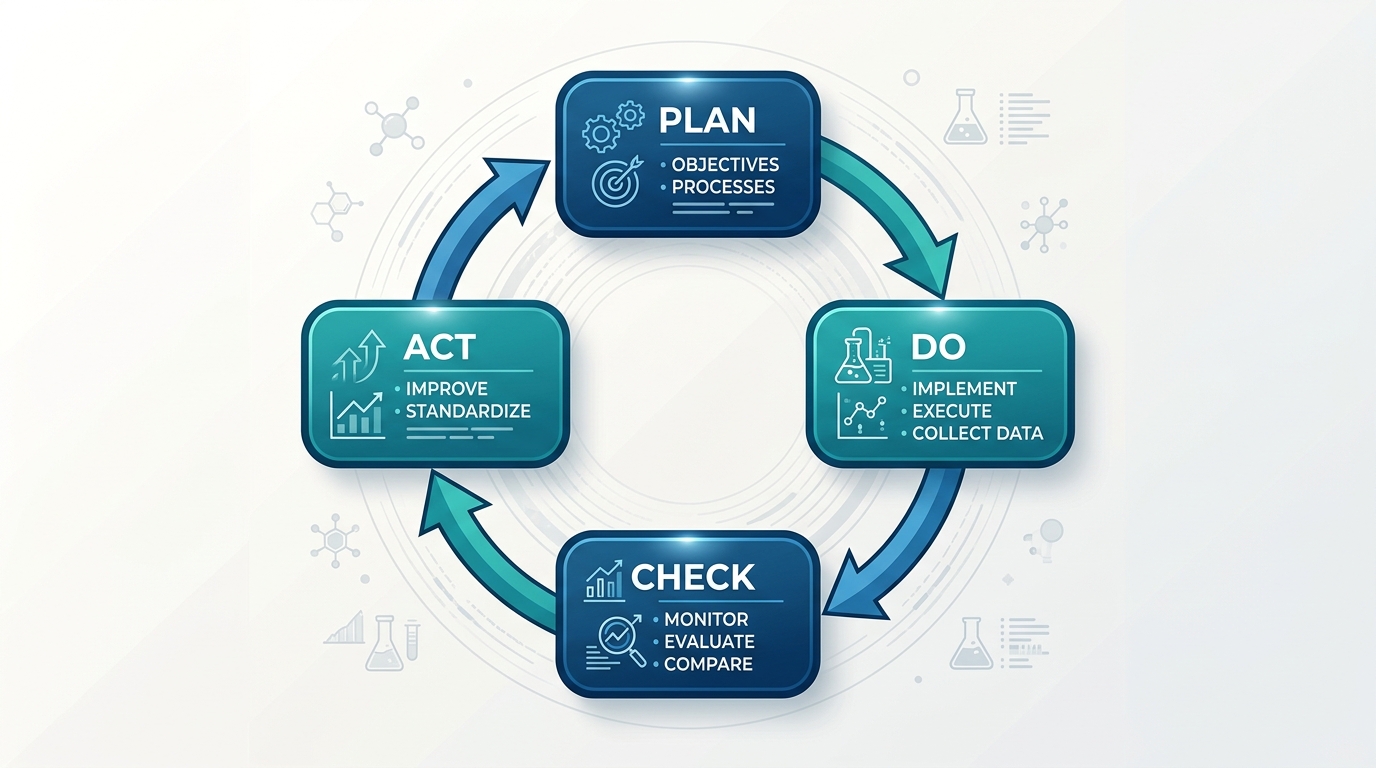
A Pharmaceutical Quality Management System is a structured system of processes, responsibilities, procedures, controls, resources, and performance measures designed to ensure that pharmaceutical products consistently meet established quality and regulatory requirements.
An effective PQMS provides assurance that:
•
Products are consistently manufactured and controlled according to approved requirements.
•
Manufacturing processes are appropriately designed, qualified, validated, and controlled.
•
Materials and suppliers meet defined quality requirements.
•
Laboratory testing is scientifically sound and reliable.
•
Equipment, facilities, utilities, and computerized systems are appropriately controlled.
•
Deviations and quality events are properly investigated.
•
Corrective and Preventive Actions (CAPA) address root causes effectively.
•
Changes are assessed and implemented through formal change control.
•
Data and records are accurate, complete, attributable, and reliable.
•
Complaints and product quality issues are investigated promptly.
•
Product recalls can be effectively managed when necessary.
•
Senior management periodically evaluates the performance and effectiveness of the quality system.
The ultimate objective is to ensure that patients receive medicines of consistent quality and that product quality is maintained throughout the pharmaceutical lifecycle.
Key Objectives of a Pharmaceutical QMS
A pharmaceutical QMS should support several fundamental objectives.
1. Patient Safety
The primary objective of pharmaceutical quality management is protecting patients by ensuring that medicines are safe, effective, and consistently manufactured according to approved specifications.
2. Regulatory Compliance
Pharmaceutical companies operate in a highly regulated environment. The QMS provides the framework for compliance with applicable GMP requirements, regulatory expectations, marketing authorizations, pharmacopoeial requirements, and other applicable standards.
3. Product Quality
The QMS establishes controls that ensure products consistently meet approved specifications and predefined quality attributes.
4. Process Consistency
Manufacturing processes should be reproducible and controlled so that every batch meets established requirements.
5. Risk Management
Potential quality risks should be identified, evaluated, controlled, communicated, and periodically reviewed.
6. Continuous Improvement
The pharmaceutical quality system should continually evolve based on process performance, deviations, complaints, audit findings, regulatory observations, scientific knowledge, and emerging risks.
Regulatory Foundation of the Pharmaceutical QMS
Pharmaceutical quality systems are influenced by multiple regulatory and industry frameworks. Depending on the market and product type, organizations may need to consider requirements and expectations from authorities and standards such as:
•
US Food and Drug Administration (FDA) – e.g., 21 CFR Parts 210 and 211
•
European Medicines Agency (EMA) – e.g., EU GMP Guidelines
•
International Council for Harmonisation (ICH) – e.g., ICH Q10 (Pharmaceutical Quality System)
•
World Health Organization (WHO) – GMP Guidelines
•
International Organization for Standardization (ISO) – e.g., ISO 9001, ISO 13485
ICH Q10, in particular, provides a globally harmonized framework for establishing an effective pharmaceutical quality system that applies across the entire product lifecycle.
The Pharmaceutical Lifecycle and the QMS
A comprehensive pharmaceutical QMS is not limited to commercial manufacturing. It spans the entire product lifecycle, which ICH Q10 defines in four main phases:
- Pharmaceutical Development: Designing the product and its manufacturing process to consistently deliver the intended performance and meet patient needs.
- Technology Transfer: Transferring product and process knowledge from development to manufacturing, or from one manufacturing site to another.
- Commercial Manufacturing: Ensuring that the product is consistently manufactured in accordance with established quality standards and regulatory requirements.
- Product Discontinuation: Managing the end of the product's lifecycle, including document retention, sample retention, and continued product assessment if required.
The QMS should be appropriately adapted to the specific phase of the lifecycle, recognizing that the level of formality and documentation typically increases as a product moves from development toward commercialization.
Core Elements of a Pharmaceutical QMS
While specific QMS designs vary among organizations, a robust pharmaceutical QMS typically incorporates the following core elements and subsystems.
1. Management Responsibilities
Senior management has the ultimate responsibility for the effectiveness of the pharmaceutical quality system. Their active involvement is crucial for:
•
Establishing the company's quality policy and objectives.
•
Ensuring that adequate resources (personnel, equipment, facilities) are available.
•
Communicating the importance of quality throughout the organization.
•
Conducting periodic Management Reviews to assess the performance of the QMS and identify opportunities for improvement.
2. Quality Manual and Documentation System
The QMS should be clearly documented. This typically starts with a Quality Manual that describes the overall quality system, its scope, management responsibilities, and the core processes.
Below the Quality Manual, the documentation system includes:
•
Policies: High-level statements of the organization's intentions and rules.
•
Standard Operating Procedures (SOPs): Detailed instructions for performing specific tasks.
•
Work Instructions: Step-by-step guidance for specific operations.
•
Specifications: Requirements that materials, products, or processes must meet.
•
Protocols and Reports: Documents used for validation, qualification, and studies.
•
Records: Evidence of activities performed (e.g., batch records, logbooks, testing results).
3. Personnel and Training
People are a critical component of any quality system. The QMS must ensure that:
•
Personnel have the necessary qualifications, education, and experience to perform their assigned duties.
•
Comprehensive training programs are in place for cGMP, specific job functions, and relevant procedures.
•
Training effectiveness is evaluated.
•
Personnel understand their role in maintaining product quality and patient safety.
4. Facility and Equipment Controls
Manufacturing and testing environments must be suitable for their intended purpose. The QMS governs:
•
Facility design, construction, and maintenance to prevent contamination and mix-ups.
•
Environmental monitoring of critical manufacturing areas (e.g., cleanrooms).
•
Equipment qualification (Design, Installation, Operational, and Performance Qualification – DQ, IQ, OQ, PQ).
•
Calibration of instruments and measuring devices.
•
Preventive and corrective maintenance programs.
5. Materials Management and Supplier Quality
The quality of a pharmaceutical product is highly dependent on the quality of its starting materials. The QMS must include processes for:
•
Evaluating, approving, and monitoring suppliers and contract manufacturers.
•
Establishing quality agreements with critical suppliers.
•
Receiving, sampling, testing, and releasing incoming materials (Active Pharmaceutical Ingredients, excipients, packaging materials).
•
Controlling the storage and handling of materials to prevent degradation or contamination.
6. Production and Process Controls
Manufacturing processes must be designed and controlled to ensure consistent product quality. This includes:
•
Process validation to demonstrate that manufacturing processes consistently produce products meeting predetermined specifications.
•
Detailed, approved Master Batch Records and executed Batch Manufacturing Records.
•
In-process controls and monitoring during production.
•
Controls to prevent cross-contamination (e.g., cleaning validation, dedicated equipment, air handling systems).
•
Packaging and labeling controls to prevent mix-ups.
7. Laboratory Controls
Quality Control (QC) laboratories play a vital role in evaluating materials and products. The QMS governs laboratory operations, including:
•
Analytical method validation to ensure testing procedures are accurate, precise, and reliable.
•
Testing of raw materials, in-process materials, and finished products against approved specifications.
•
Stability testing programs to determine product shelf-life and storage conditions.
•
Management of reference standards, reagents, and samples.
•
Investigation of Out-of-Specification (OOS) and Out-of-Trend (OOT) results.
8. Quality Event Management (Deviations, CAPA, Complaints)
No system is perfect, and unexpected events will occur. How an organization handles these events is a critical measure of its QMS effectiveness.
•
Deviations: The QMS must provide a mechanism for identifying, documenting, and investigating any departures from approved procedures or specifications. Investigations should aim to identify the root cause of the deviation.
•
Corrective and Preventive Actions (CAPA): Based on investigation findings, CAPAs are implemented to correct existing problems and prevent their recurrence. The effectiveness of CAPAs must be evaluated after implementation.
•
Complaints: The QMS must include procedures for receiving, evaluating, and investigating customer complaints related to product quality. Serious complaints may trigger product recalls.
9. Change Management
Changes in the pharmaceutical industry are inevitable (e.g., new equipment, process improvements, updated specifications, supplier changes). However, uncontrolled changes can introduce significant risk. The QMS must include a formal Change Control process to:
•
Evaluate the potential impact of proposed changes on product quality, safety, efficacy, and regulatory compliance.
•
Ensure changes are reviewed and approved by appropriate personnel (including the Quality Unit) before implementation.
•
Identify necessary actions (e.g., revalidation, regulatory submissions, training) required to support the change.
10. Audits and Inspections
Audits are essential for assessing QMS compliance and effectiveness.
•
Internal Audits (Self-Inspections): The organization should conduct regular internal audits of its departments and processes to identify compliance gaps and areas for improvement.
•
External Audits: The organization must be prepared for inspections by regulatory authorities (e.g., FDA, EMA) and audits by customers.
•
Supplier Audits: The organization should audit its critical suppliers and contract service providers.
Thank You Our Valued Partners





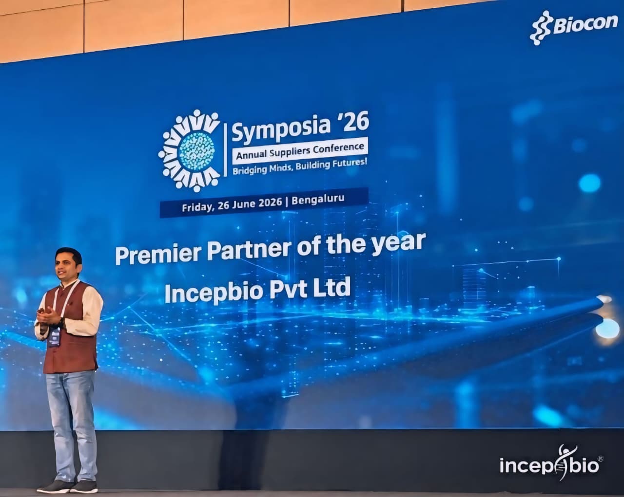







.jpg)




.jpg)


.jpg)









.jpg)















.jpg)